Table of Contents
Raspberry Pi Pico and RFID:

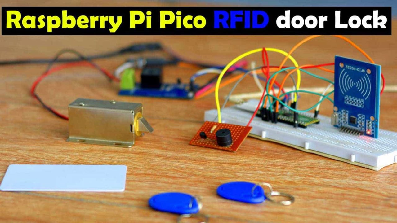
Raspberry Pi Pico and RFID based Door Lock Control System– In this tutorial, you will learn how to control an electronic door lock using Raspberry Pi Pico, a one-channel relay module, a 5v buzzer, and an MFRC522 RFID Reader module.
Just similar to an Arduino, ESP32, ESP8266, and STM32, Raspberry Pi Pico is also a controller board based on the RP2040 microcontroller, through the programming of which, you can control almost anything. And apart from this, you can also monitor different types of analog and digital sensors as well. In case you are using a Raspberry Pi Pico for the first time, I would definitely recommend you to read my “Getting started tutorial on Raspberry Pi Pico”. In this article, I have explained and attempted to shed light on almost everything in the article that a beginner must be acquainted with. In this getting started tutorial, I did 10 different beginners level projects.
I am sure almost 99.9% of people must be aware of the door locks, while, the remaining 0.1% are those people, who unluckily reside in such regions, where, I am afraid, people do not even know what actually the doors are?

Anyway, here is an ordinary door lock, which you can easily open or close with the help of a key.

Whereas, this is an Elock or Electronic Door lock, which you can simply control electronically. I am not using this electronic lock for the first time. I have used it on many occasions during my different projects. Most recently, I used the same particular electronic door lock with an ESP32 camera module, I have also used the same exact electronic door lock with the ESP8266 Wifi module. And, of course, needless to say, I have also used it with the Arduino.
Anyways, before I share with you the circuit diagram and code, first let’s watch the Raspberry Pi Pico and RFID based Door lock control system in action.
Altium Designer + Altium 365 + Octopart:

Altium 365lets you hold the fastest design reviews ever. Share your designs from anywhere andwith anyone with a single click. it’s easy, leave a comment tagging your teammate and they’ll instantly receive an email with a link to the design. Anyone you invite can open the design using a web browser. Using the browser interface, you’re able to comment, markup, cross probe, inspect, and more. Comments are attached directly to the project, making them viewable within Altium designer as well as through the browser interface. Design, share, and manufacture, all in the same space with nothing extra to install or configure. Connect to the platform directly fromAltium Designerwithout changing how you already design electronics.Altium 365requires no additional licenses and comes included with your subscription plan.
Get real-time component insights as you design with Octopart built into Altium 365. Octopart is the fastest search engine for electronic parts and gives you the most up-to-date part data like specs, datasheets, cad models, and how much the part costs at different amounts etc. Right in the design environment so you can focus on your designs. Start withAltium DesignerandActivate Altium 365. Search for electronic parts on Octopart.

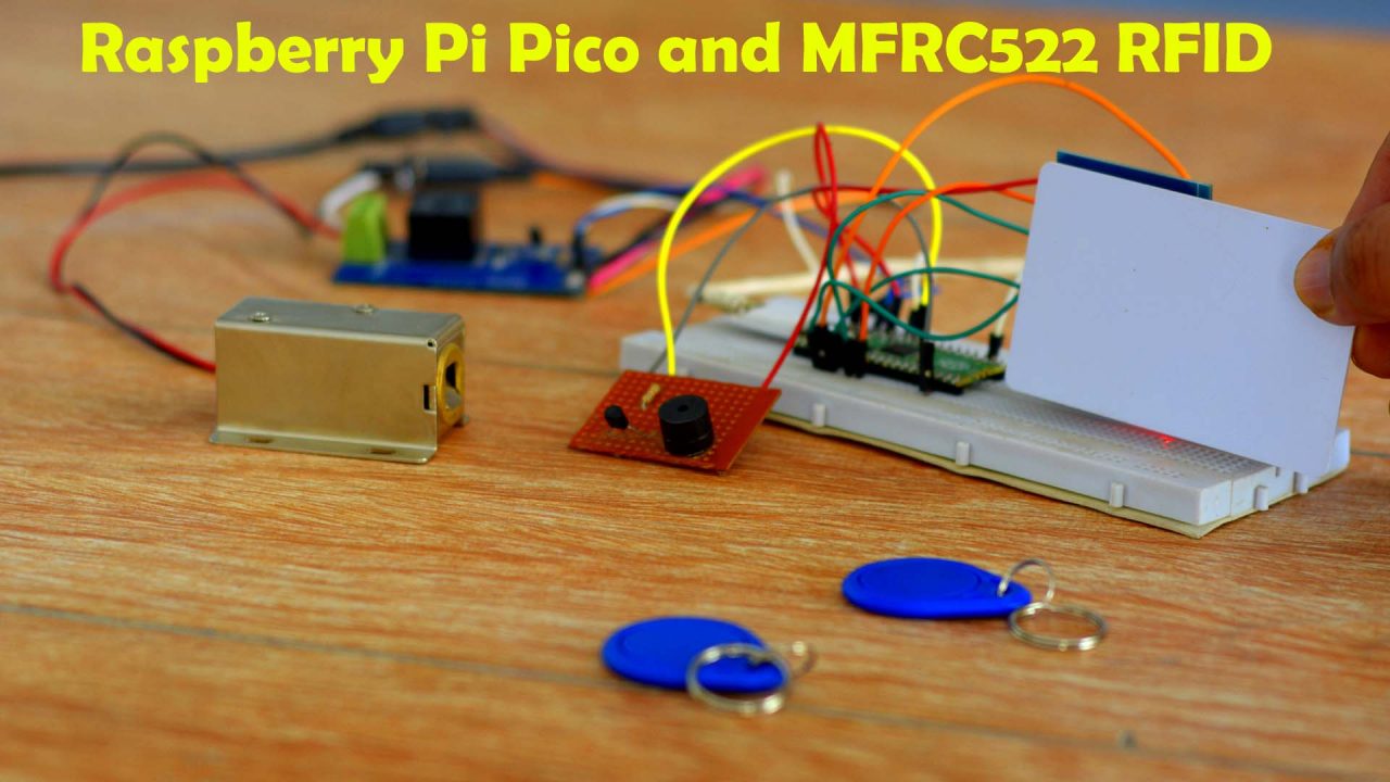
I have already powered up the entire system. Right now I have one RFID card and two RFID key chains. One of these key chains is authorized which I can use to open the electronic door lock, while the other one is unauthorized. When the unauthorized RFID card or keychain is used the buzzer is immediately turned ON.
Anyways, right now you can see, that when no authorized RFID card is used the Electronic door lock remains closed. Whereas when the authorized RFID card is used, the electronic door lock is opened.

You have obviously watched my video tutorial given at the end of this article, how easily we can control an electronic door lock using the Raspberry Pi Pico and RFID module. I am sure by now you might have got an idea of how does this system works. So, without any further delay, let’s get started!!!
Amazon Links:
Other Tools and Components:
Super Starter kit for Beginners
PCB small portable drill machines
*Please Note: These are affiliate links. I may make a commission if you buy the components through these links. I would appreciate your support in this way!
Raspberry Pi Pico and RFID, Circuit Diagram:

The SDA, SCK, MOSI, MISO, and RST pins of the MFRC522 RFID reader module are connected with the Raspberry Pi Pico GPIO pins 5, 6, 7, 4, and 3 respectively. And obviously the 3.3V and GND pins of the RFID module are connected with the Raspberry Pi Pico 3.3V and GND pins.
A one-channel relay module is controlled using the GP28 pin on the Raspberry Pi Pico. This is an SPDT-type relay. SPDT stands for single pole and double throw. The 12V wire to the Electronic door lock goes through this relay.
The 5V buzzer is controlled using the GP27 pin on the Raspberry Pi Pico. The 2n2222 NPN transistor and 10K resistor makes the driver circuit which is used to control the buzzer.
Raspberry Pi Pico and RFID, Python Programming:
Connect Raspberry Pi Pico with the Laptop.
Copy the code given below.
Mfrc522.py Code:
from machine import Pin, SPIfrom os import unameclass MFRC522: DEBUG = False OK = 0 NOTAGERR = 1 ERR = 2 REQIDL = 0x26 REQALL = 0x52 AUTHENT1A = 0x60 AUTHENT1B = 0x61 PICC_ANTICOLL1 = 0x93 PICC_ANTICOLL2 = 0x95 PICC_ANTICOLL3 = 0x97 def __init__(self, sck, mosi, miso, rst, cs,baudrate=1000000,spi_id=0): self.sck = Pin(sck, Pin.OUT) self.mosi = Pin(mosi, Pin.OUT) self.miso = Pin(miso) self.rst = Pin(rst, Pin.OUT) self.cs = Pin(cs, Pin.OUT) self.rst.value(0) self.cs.value(1) board = uname()[0] if board == 'WiPy' or board == 'LoPy' or board == 'FiPy': self.spi = SPI(0) self.spi.init(SPI.MASTER, baudrate=1000000, pins=(self.sck, self.mosi, self.miso)) elif (board == 'esp8266') or (board == 'esp32'): self.spi = SPI(baudrate=100000, polarity=0, phase=0, sck=self.sck, mosi=self.mosi, miso=self.miso) self.spi.init() elif board == 'rp2': self.spi = SPI(spi_id,baudrate=baudrate,sck=self.sck, mosi= self.mosi, miso= self.miso) else: raise RuntimeError("Unsupported platform") self.rst.value(1) self.init() def _wreg(self, reg, val): self.cs.value(0) self.spi.write(b'%c' % int(0xff & ((reg << 1) & 0x7e))) self.spi.write(b'%c' % int(0xff & val)) self.cs.value(1) def _rreg(self, reg): self.cs.value(0) self.spi.write(b'%c' % int(0xff & (((reg << 1) & 0x7e) | 0x80))) val = self.spi.read(1) self.cs.value(1) return val[0] def _sflags(self, reg, mask): self._wreg(reg, self._rreg(reg) | mask) def _cflags(self, reg, mask): self._wreg(reg, self._rreg(reg) & (~mask)) def _tocard(self, cmd, send): recv = [] bits = irq_en = wait_irq = n = 0 stat = self.ERR if cmd == 0x0E: irq_en = 0x12 wait_irq = 0x10 elif cmd == 0x0C: irq_en = 0x77 wait_irq = 0x30 self._wreg(0x02, irq_en | 0x80) self._cflags(0x04, 0x80) self._sflags(0x0A, 0x80) self._wreg(0x01, 0x00) for c in send: self._wreg(0x09, c) self._wreg(0x01, cmd) if cmd == 0x0C: self._sflags(0x0D, 0x80) i = 2000 while True: n = self._rreg(0x04) i -= 1 if ~((i != 0) and ~(n & 0x01) and ~(n & wait_irq)): break self._cflags(0x0D, 0x80) if i: if (self._rreg(0x06) & 0x1B) == 0x00: stat = self.OK if n & irq_en & 0x01: stat = self.NOTAGERR elif cmd == 0x0C: n = self._rreg(0x0A) lbits = self._rreg(0x0C) & 0x07 if lbits != 0: bits = (n - 1) * 8 + lbits else: bits = n * 8 if n == 0: n = 1 elif n > 16: n = 16 for _ in range(n): recv.append(self._rreg(0x09)) else: stat = self.ERR return stat, recv, bits def _crc(self, data): self._cflags(0x05, 0x04) self._sflags(0x0A, 0x80) for c in data: self._wreg(0x09, c) self._wreg(0x01, 0x03) i = 0xFF while True: n = self._rreg(0x05) i -= 1 if not ((i != 0) and not (n & 0x04)): break return [self._rreg(0x22), self._rreg(0x21)] def init(self): self.reset() self._wreg(0x2A, 0x8D) self._wreg(0x2B, 0x3E) self._wreg(0x2D, 30) self._wreg(0x2C, 0) self._wreg(0x15, 0x40) self._wreg(0x11, 0x3D) self.antenna_on() def reset(self): self._wreg(0x01, 0x0F) def antenna_on(self, on=True): if on and ~(self._rreg(0x14) & 0x03): self._sflags(0x14, 0x03) else: self._cflags(0x14, 0x03) def request(self, mode): self._wreg(0x0D, 0x07) (stat, recv, bits) = self._tocard(0x0C, [mode]) if (stat != self.OK) | (bits != 0x10): stat = self.ERR return stat, bits def anticoll(self,anticolN): ser_chk = 0 ser = [anticolN, 0x20] self._wreg(0x0D, 0x00) (stat, recv, bits) = self._tocard(0x0C, ser) if stat == self.OK: if len(recv) == 5: for i in range(4): ser_chk = ser_chk ^ recv[i] if ser_chk != recv[4]: stat = self.ERR else: stat = self.ERR return stat, recv def PcdSelect(self, serNum,anticolN): backData = [] buf = [] buf.append(anticolN) buf.append(0x70) #i = 0 ###xorsum=0; for i in serNum: buf.append(i) #while i<5: # buf.append(serNum[i]) # i = i + 1 pOut = self._crc(buf) buf.append(pOut[0]) buf.append(pOut[1]) (status, backData, backLen) = self._tocard( 0x0C, buf) if (status == self.OK) and (backLen == 0x18): return 1 else: return 0 def SelectTag(self, uid): byte5 = 0 #(status,puid)= self.anticoll(self.PICC_ANTICOLL1) #print("uid",uid,"puid",puid) for i in uid: byte5 = byte5 ^ i puid = uid + [byte5] if self.PcdSelect(puid,self.PICC_ANTICOLL1) == 0: return (self.ERR,[]) return (self.OK , uid) def tohexstring(self,v): s="[" for i in v: if i != v[0]: s = s+ ", " s=s+ "0x{:02X}".format(i) s= s+ "]" return s def SelectTagSN(self): valid_uid=[] (status,uid)= self.anticoll(self.PICC_ANTICOLL1) #print("Select Tag 1:",self.tohexstring(uid)) if status != self.OK: return (self.ERR,[]) if self.DEBUG: print("anticol(1) {}".format(uid)) if self.PcdSelect(uid,self.PICC_ANTICOLL1) == 0: return (self.ERR,[]) if self.DEBUG: print("pcdSelect(1) {}".format(uid)) #check if first byte is 0x88 if uid[0] == 0x88 : #ok we have another type of card valid_uid.extend(uid[1:4]) (status,uid)=self.anticoll(self.PICC_ANTICOLL2) #print("Select Tag 2:",self.tohexstring(uid)) if status != self.OK: return (self.ERR,[]) if self.DEBUG: print("Anticol(2) {}".format(uid)) rtn = self.PcdSelect(uid,self.PICC_ANTICOLL2) if self.DEBUG: print("pcdSelect(2) return={} uid={}".format(rtn,uid)) if rtn == 0: return (self.ERR,[]) if self.DEBUG: print("PcdSelect2() {}".format(uid)) #now check again if uid[0] is 0x88 if uid[0] == 0x88 : valid_uid.extend(uid[1:4]) (status , uid) = self.anticoll(self.PICC_ANTICOLL3) #print("Select Tag 3:",self.tohexstring(uid)) if status != self.OK: return (self.ERR,[]) if self.DEBUG: print("Anticol(3) {}".format(uid)) if self.MFRC522_PcdSelect(uid,self.PICC_ANTICOLL3) == 0: return (self.ERR,[]) if self.DEBUG: print("PcdSelect(3) {}".format(uid)) valid_uid.extend(uid[0:5]) # if we are here than the uid is ok # let's remove the last BYTE whic is the XOR sum return (self.OK , valid_uid[:len(valid_uid)-1]) #return (self.OK , valid_uid) def auth(self, mode, addr, sect, ser): return self._tocard(0x0E, [mode, addr] + sect + ser[:4])[0] def authKeys(self,uid,addr,keyA=None, keyB=None): status = self.ERR if keyA is not None: status = self.auth(self.AUTHENT1A, addr, keyA, uid) elif keyB is not None: status = self.auth(self.AUTHENT1B, addr, keyB, uid) return status def stop_crypto1(self): self._cflags(0x08, 0x08) def read(self, addr): data = [0x30, addr] data += self._crc(data) (stat, recv, _) = self._tocard(0x0C, data) return stat, recv def write(self, addr, data): buf = [0xA0, addr] buf += self._crc(buf) (stat, recv, bits) = self._tocard(0x0C, buf) if not (stat == self.OK) or not (bits == 4) or not ((recv[0] & 0x0F) == 0x0A): stat = self.ERR else: buf = [] for i in range(16): buf.append(data[i]) buf += self._crc(buf) (stat, recv, bits) = self._tocard(0x0C, buf) if not (stat == self.OK) or not (bits == 4) or not ((recv[0] & 0x0F) == 0x0A): stat = self.ERR return stat def writeSectorBlock(self,uid, sector, block, data, keyA=None, keyB = None): absoluteBlock = sector * 4 + (block % 4) if absoluteBlock > 63 : return self.ERR if len(data) != 16: return self.ERR if self.authKeys(uid,absoluteBlock,keyA,keyB) != self.ERR : return self.write(absoluteBlock, data) return self.ERR def readSectorBlock(self,uid ,sector, block, keyA=None, keyB = None): absoluteBlock = sector * 4 + (block % 4) if absoluteBlock > 63 : return self.ERR, None if self.authKeys(uid,absoluteBlock,keyA,keyB) != self.ERR : return self.read(absoluteBlock) return self.ERR, None def MFRC522_DumpClassic1K(self,uid, Start=0, End=64, keyA=None, keyB=None): for absoluteBlock in range(Start,End): status = self.authKeys(uid,absoluteBlock,keyA,keyB) # Check if authenticated print("{:02d} S{:02d} B{:1d}: ".format(absoluteBlock, absoluteBlock//4 , absoluteBlock % 4),end="") if status == self.OK: status, block = self.read(absoluteBlock) if status == self.ERR: break else: for value in block: print("{:02X} ".format(value),end="") print(" ",end="") for value in block: if (value > 0x20) and (value < 0x7f): print(chr(value),end="") else: print('.',end="") print("") else: break if status == self.ERR: print("Authentication error") return self.ERR return self.OKSo, after copying the above code. Open the Thonny IDE and click on the new file. And paste this code. Save this code in the Raspberry Pi Pico with the name mfrc522.py.
Now, copy the code given below.
main.py code:
from mfrc522 import MFRC522 import utimefrom machine import Pinlock =Pin(28,Pin.OUT)buzzer = Pin(27, Pin.OUT)def uidToString(uid): mystring = "" for i in uid: mystring = "%02X" % i + mystring return mystring rc522 = MFRC522(spi_id=0,sck=6,miso=4,mosi=7,cs=5,rst=3)print("")print("Place the card")print("")while True: (stat, tag_type) = rc522.request(rc522.REQALL) if stat == rc522.OK: (status, raw_uid) = rc522.SelectTagSN() if stat == rc522.OK: rfid_data = "{:02x}{:02x}{:02x}{:02x}".format(raw_uid[0], raw_uid[1], raw_uid[2], raw_uid[3]) print("Card detected! UID: {}".format(rfid_data)) if rfid_data == "c645224b": lock.value(1) utime.sleep(5) lock.value(0) elif rfid_data == "4247b01e": lock.value(1) utime.sleep(5) lock.value(0) else: buzzer.value(1) utime.sleep(1) buzzer.value(0)After you have copied the code, again go to the Thonny IDE and again click on the new file and paste this code. This time save this code in Raspberry Pi Pico with the name main.py
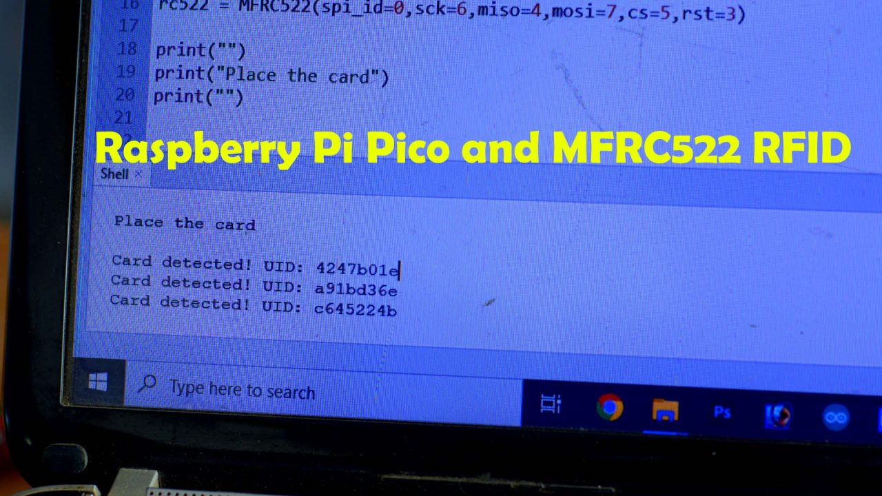
Now, finally you can click on the play button. You will be prompted, to place the card as you can see in the image given below. Swipe the RFID cards, tags, or key chains to find the UIDs.
My UIDs are:
4247b01e
a91bd36e
c645224b

You can see in the main.py code, I have used the same IDs to control the electronic door lock. You can find the identification numbers of your RFID cards using the same method and then update the main.py code accordingly. If you face any issues then watch my video tutorial given below.
